Room Scale Metaverse
Motivation
The last 5 years VR technologies have become more and more available to people. The first applications were in the video games industry but due to the recent advancement in technology they have started to gain a lot of scientific value. The scientific value of Virtual and Augmented reality has been realised and many systems have been created. Most of the current work in the field of Mixed Reality (Augmented Reality and Virtual Reality) is treating both technologies in an isolated way. They focus on either using only VR or only AR to interact or collaborate on a task. However, similar to our current workflow where we use different types of technologies to interact and collaborate (e.g. smartphone combined with a laptop and or a tablet), Mixed Reality technologies are mainly going to extend this workflow and not replace it. The first part of the internship was to set up and calibrate the OptiTrack system and then integrate its tracking data into a Unity project. The second part was focused on writing a multiplayer Unity application, integrating all the different technologies into this scene and creating a smart space that is able to track and display any content on any of these devices. In our case, the system contained only two devices which were two Oculus Quest 2. This system could serve as a sandbox application in order to test new types of interactions that could happen between two co-located users in the virtual world.
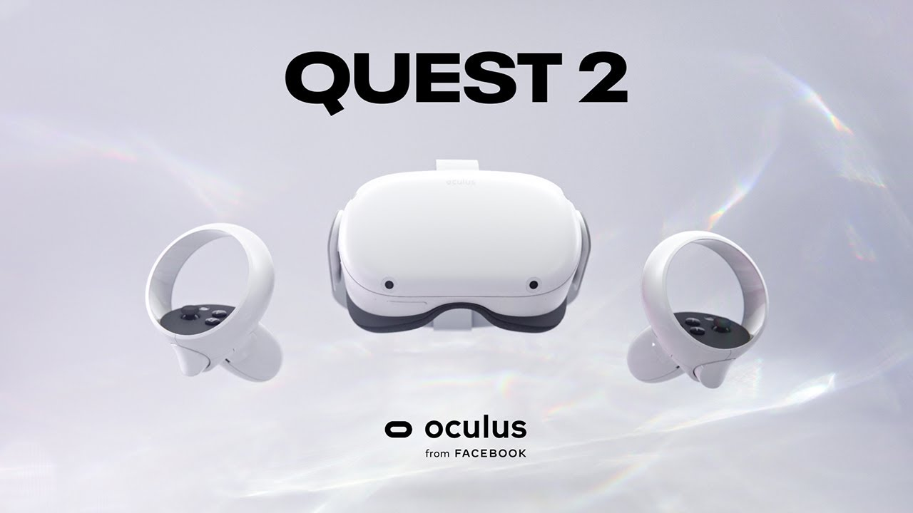
Oculus Quest 2
The latest and most advanced portable VR device. It outperforms by far its predecessor and it's even also much cheaper, thus making it the first headset that is worth having at home. Oculus Quest 2 has a much faster processor, a far better display ( 1440 x 1584 ) and fifty percent more RAM. It's technical characteristics make it possible to build even better applications than Oculus Quest 1. Oculus Quest 2 is equipped with 4 cameras that are used for the internal tracking system. They are attached on the 4 corners of the device. thus providing great tracking accuracy. The user is able to move the controllers in the real world and their representation would show in the application.
OptiTrack
Optitrack is a state of the art motion capture system. OptiTrack technology uses an array of cameras and lights to both project and receive infrared light. The projected light hits retroreflective markers and bounces back toward the cameras, making the markers appear very bright to the camera and therefore easy to identify. When sets of at least four markers are arranged in unique, 3-dimensional configurations, the software can uniquely identify these configurations and assign positions and orientations to the configurations.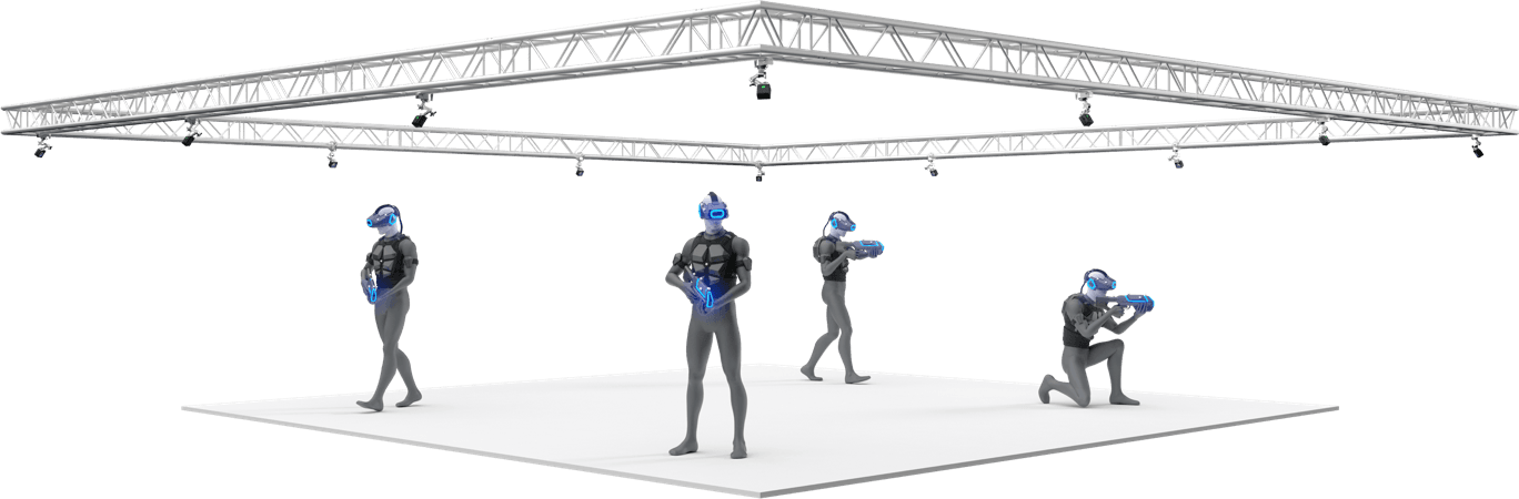
Development
The System
Our system is built using Unity and Motive. The first software is for creating a VR environment and deploying it on the Quest and the second one is how the Optitrack streams it's data into Unity.

OptiTrack Calibration
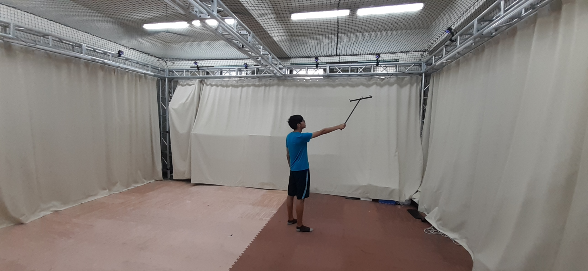
The first thing we needed to do is to calibrate the optitrack system. Optitrack calibration can be a tedious process and even a small shift in the cameras' configuration may require recalibration. The calibration process is mandatory in order for motive to function. Like in many other measurement systems, calibration is also essential for optical motion capture systems. During camera calibration, the system computes position and orientation of each camera and amounts of distortions in captured images, and they are used to construct a 3D capture volume in Motive.In order to calibrate motive, the user must prepare the software and start a specific process called "wanding" where the user moves a special stick called a wand around the area that the user sets up. When the motive collects enough data the calibration result is displayed and informs the user about the quality of the calibration, in most use cases we aim for excellent calibration which is approximately 1mm error. After finishing the calibration we use another tool called "Ground" which is a special tool that is provided by the Motive that is able to set the ground of our application.With the right calibration we are able to set up our environment with bigger precision and thus harness the true capabilities of the optitrack.
Rigidbody creation
As we mentioned previously when sets of at least four markers are arranged in unique, 3-dimensional configurations, the software can uniquely identify these configurations and assign positions and orientations to the configurations. In Motive you have the ability to label the configuration of markers and create a Rigidbody. Rigidbodies are the kind of data that optitrack can stream to Unity and it will read them directly. A rigidbody must have certain properties; its markers should be placed asymmetrically because this provides a clear distinction of orientations. Avoid placing the markers in symmetrical shapes such as squares, isosceles, or equilateral triangles. Symmetrical arrangements make asset identification difficult, and they may cause the rigid body assets to flip during capture. In our case we used some default rigidbody marker base that the Optitrack provided us with and we attached the markers on two different combinations.
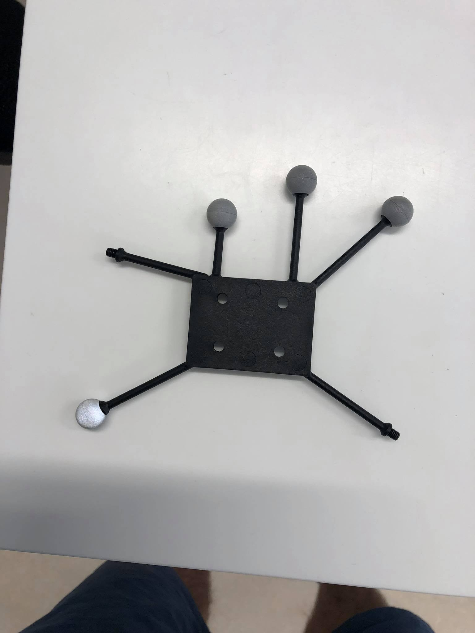
Apart from creating the physical rigidbodies we need also to define them in Motive. In Motive we select a configuration of markers and we label them as we want. In our case we used Quest 2 and Second Quest 2. Last but not least, you have to provide an id for the rigidbodies and due to simplicity we used 2 for Quest 2 and 3 for the Second Quest 2. When we created the rigidbodies we needed to find a way to transmit that data into Unity.
Streaming rigidbody into Unity
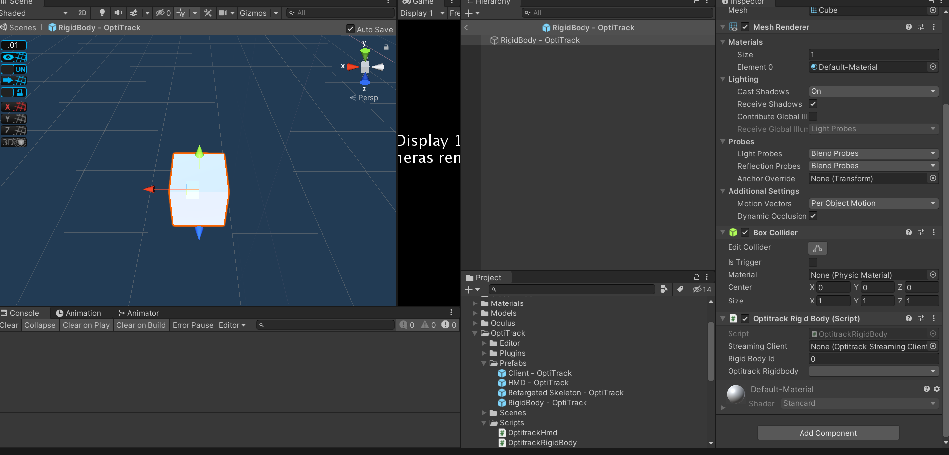
The next step is to transmit the data into Unity. Motive has a plugin for Unity that directly communicates with it. This plugin comes with prefabs that you can drag and drop directly into Unity. Specify the Ip Server and Local address that the Optitrack will stream the data. Each rigidbody is presented as a gameobject in unity, thus you can customize it's mesh and its characteristics.
OptiTrack and Oculus Quest 2
This was the biggest design challenge of the internship, the combination of an external and an internal tracking system. At first we thought of shutting down the Quest's tracking system and rely solely on the optitrack, but this situation has downsides. First of all, the Quest internal tracking system is more robust, sometimes inside the capture volume of the optitrack there are some black spots that the cameras are not able to capture fully. This means that when the user goes into one of these areas, the optitrack will stop giving information about the position and orientation of the user and this would result in the tracking system stop functioning at all. The second problem is that the Optitrack's tracking is not superior to the Quest's. The Quest uses sensor fusion to capture all of the available information about the headset, thus making it more reliable and smooth compared to the data streaming of the Optitrack. Considering the above problems, we decided that we are going to use the internal tracking of the Quest and use Optitrack as a ground truth for our system. Meaning that in order to display to other users where the Quest is, Optitrack data is going to be used. We imagine the Optitrack as a device to tell other devices where they are in space.
Implementation
Attaching rigidbody to Quest 2
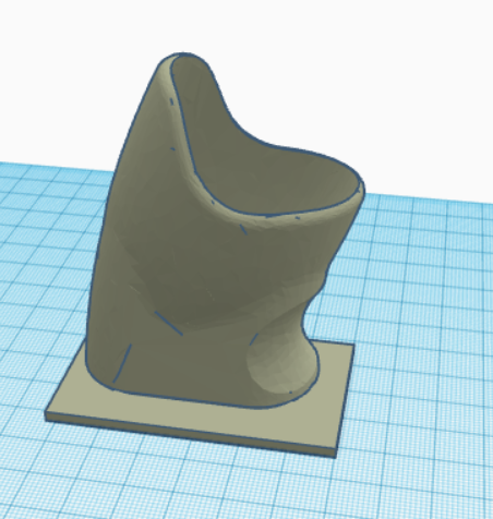
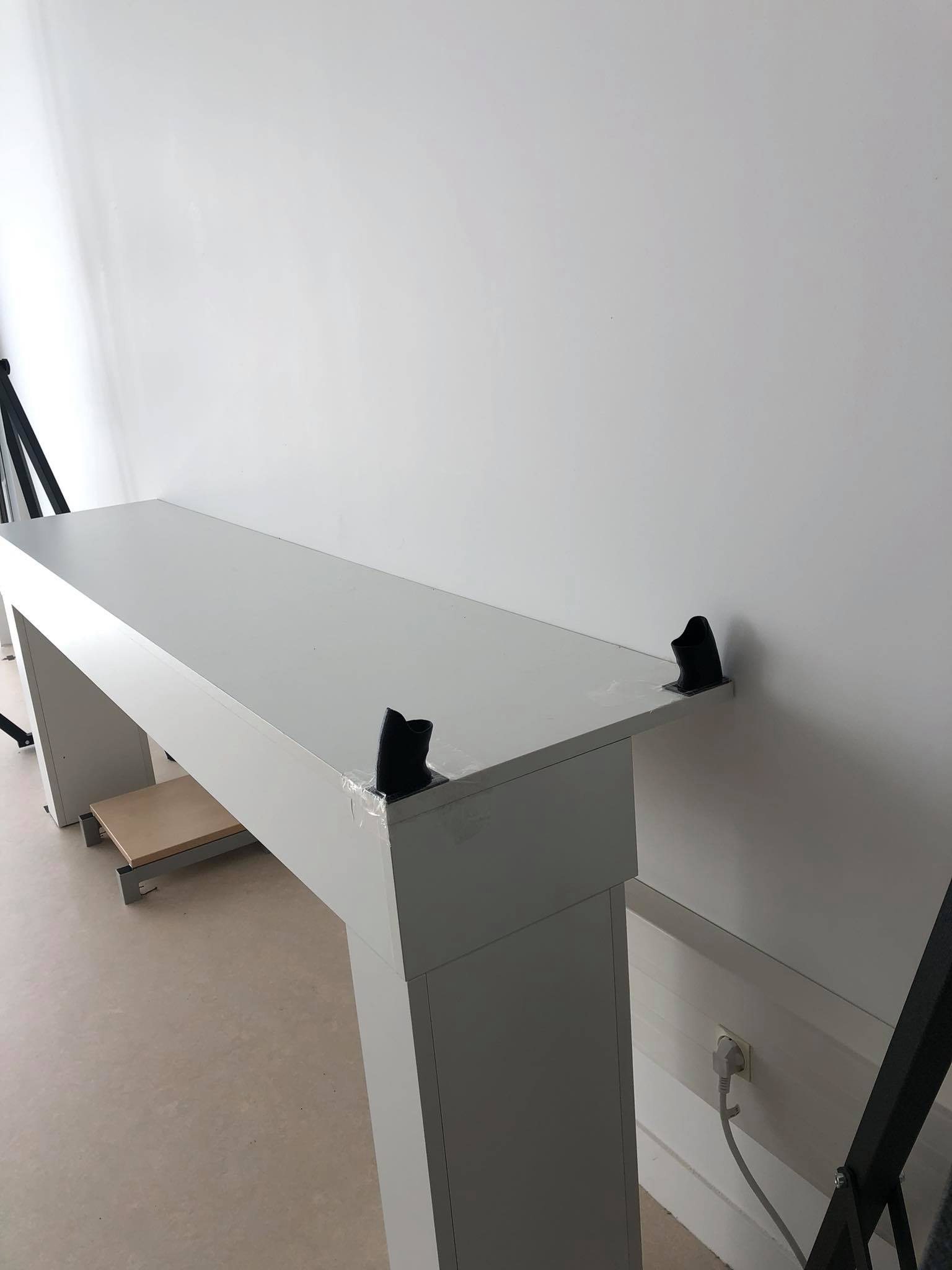
After we decided how we are going to proceed we then experimented on how we can use the Quest 2 rigidbody we defined in Motive and the physical Quest 2. We 3d printed a case that is going to hold the rigidbody. This had many design implications that we are going to analyse. The first iteration was this case:
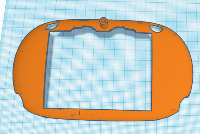
In the case that you see here we attached the previously mentioned rigidbody marker base in the tube that is on top of the case. At first, We thought that was a good example since the markers would not be covered by the headset and thus prevent occlusion. But as long as we tested we realised that sometimes the headset would behave weirdly or sometimes even make jitter effects. This weird behaviour was caused due to the fact that the optitrack marker base was covering a part of the top camera's field of view thus making the application not possible to run since the Oculus recalibrated itself too many times. The next iteration would be to attach the markers in such a way that they are not occluding the cameras and also be visible to the Optitrack. So we thought of the version below:
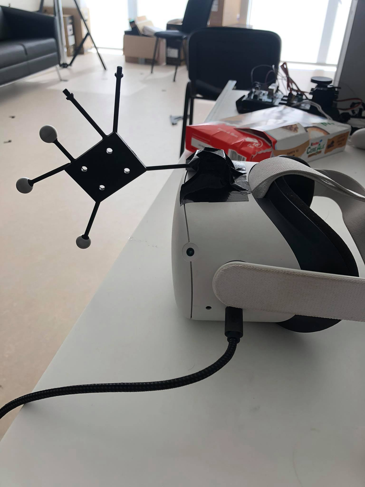
This implementation is basically a cube with holes that we attach to the Optitrack marker base. The fact that is above the headset is to avoid the previously mentioned problem, the occlusion of the Quest's Cameras. With this implementation we were able to use the Quest without having any problem with the cameras and also since the rigidbody marker base was on top of it, none of the markers were occluded.
Aligning Worlds
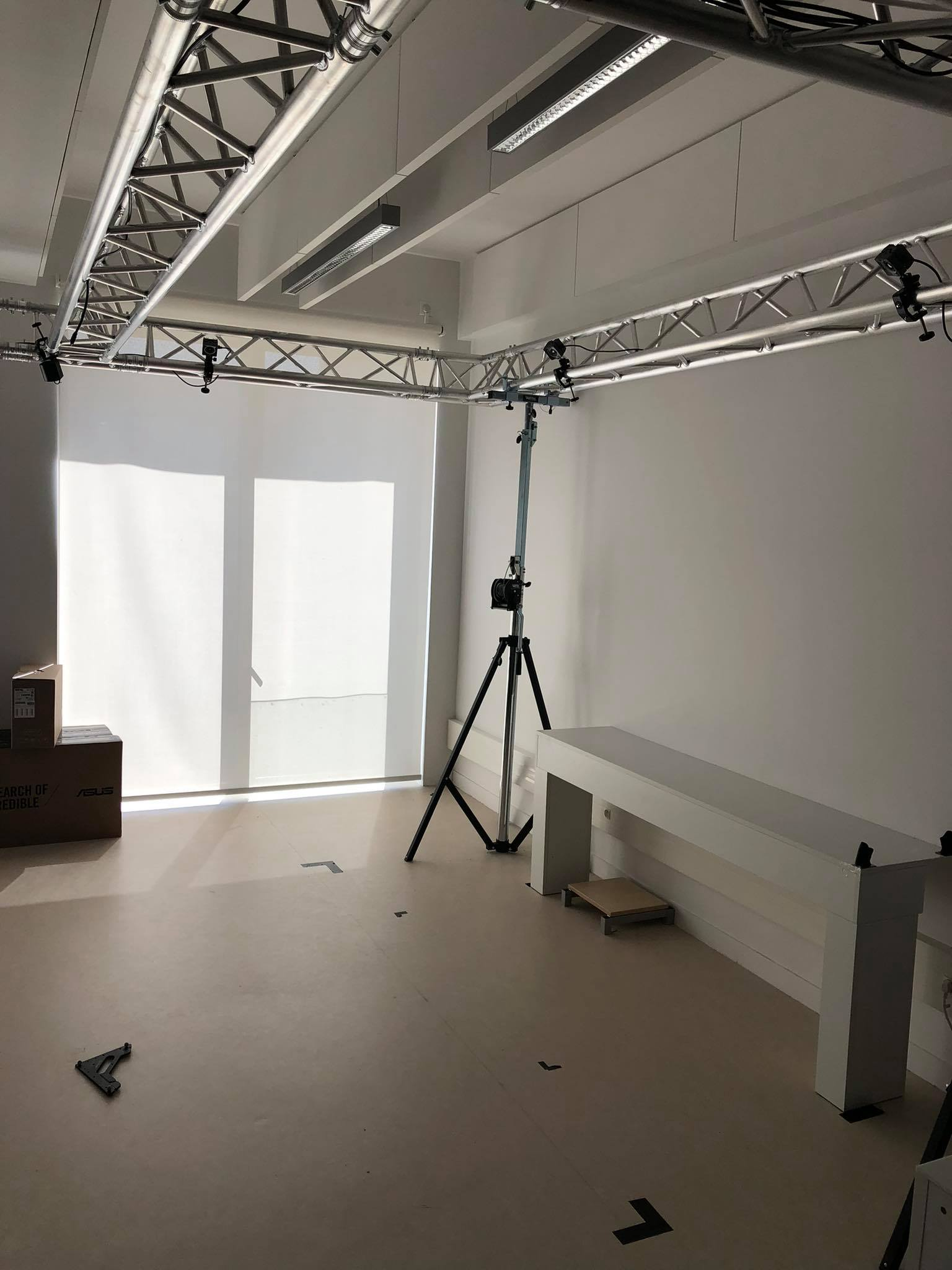
We then proceeded to do the most arduous task; aligning the Oculus Quest coordinate system with the Optitrack Coordinate system. The task of aligning their coordinate system can be rephrased also as : Aligning Oculus Quest and virtual world with the real world. At first we thought that since Optitrack can provide us with the data of the rigidbodies we can initialize the Oculus Quest at where the corresponding rigidbody is. Then rely on the movement of the Oculus Quest since it can imitate walking movement inside VR. As we tested this approach we noticed that each time we initialized the Oculus Quest it had a different coordinate system and it is dependent on its starting point. This created a huge problem since we didn't want to rely only on the optitrack for the Quest tracking, so an alternative was to create an alignment/calibration process and translate and rotate the Oculus Quest so that it matches the coordinates of the Optitrack. The first thing we needed to do is to map our room to one to one both in the virtual and the real world. This was done using the Optitrack. We placed the markers in different places around the room and since they streamed their data in Unity we could map their exact positions. We placed markers throughout the room and we then proceeded to create the environment in Unity. Due to simplification we wanted only to map the tracking area of the Optitrack since this is the area we are going to be using in our project.

Calibration Process
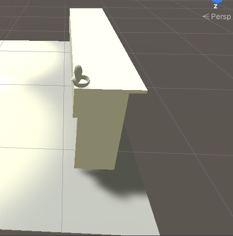
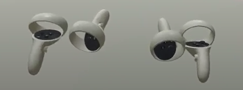
As we mentioned earlier we needed to create a calibration process because each time we initiated the Oculus Quest it had a different coordinate system. The calibration process we thought of was simple. Since the scene was 1:1 we needed to define a physical and a virtual model and then translate and rotate the headset accordingly so that they would be aligned. At First, that model would be the Oculus right controller. The user would have to place the controller in the exact same position in the physical as the controller in the virtual world and then just press A so that the two coordinates align. The controller was first located at the edge of the table and on top of it.
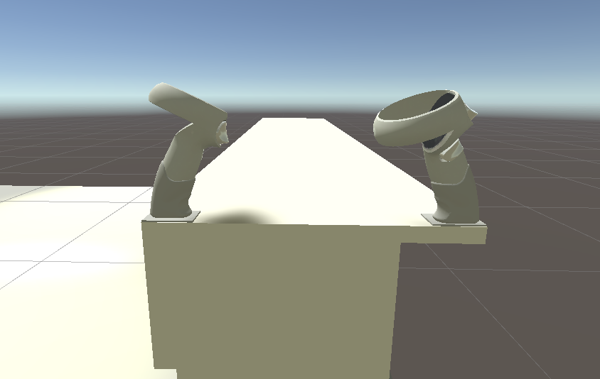
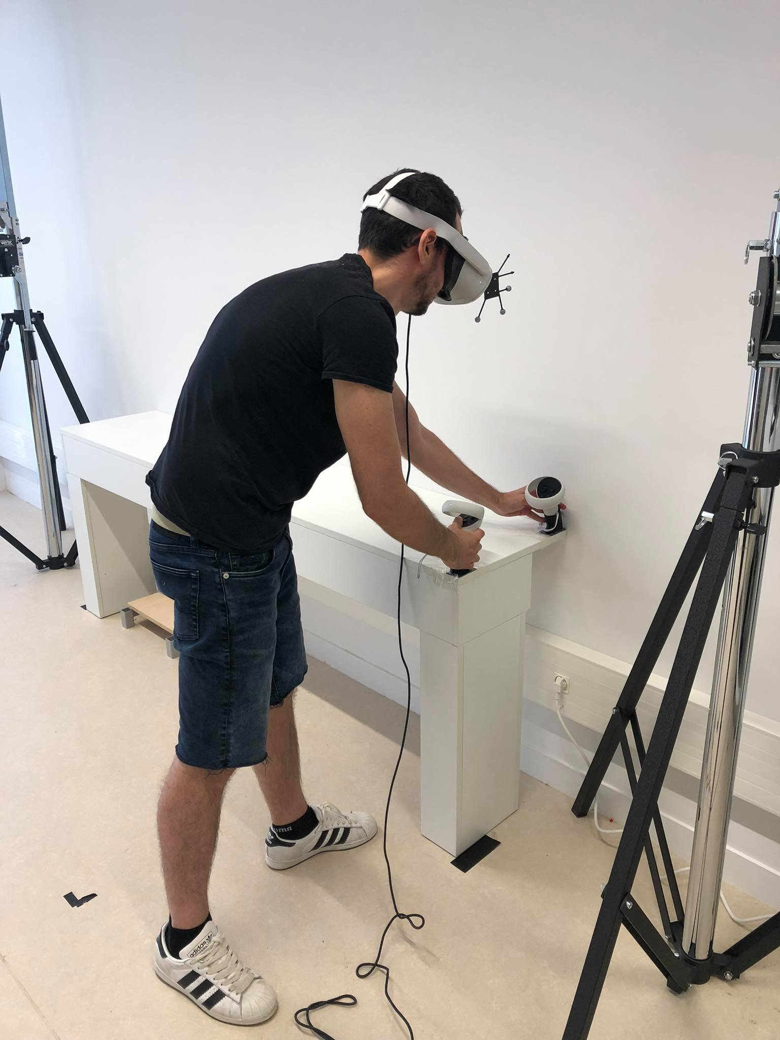
This fixed the problem of the position now the player could move around the area freely but it didn't fix the rotation. Since we are using just one controller to align the environment the rotation was not perfect and even 1 degree difference could mean 5cm deviation in the virtual world. So we added a second controller into the scene, this time the user would have to manually place the two controllers in the corresponding positions and rotate himself/herself so that both the real and virtual controller would match. This time the controllers would be located at the front of the table as shown in the picture below.
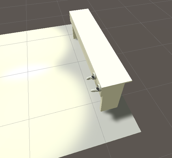
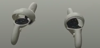
This resolved the issue of our rotations since now we are using two reference points instead of one but we found out that since we wanted precision, we could not let the user manually adjust and determine himself, when the two controllers are aligned. We needed a fixed way to determine where the controllers should be placed and based on these fixed places we could derive more precise information about how much we should change the transformation matrix of our player. We then proceeded to 3d print some parts that would fit the controllers
These controller holders would be placed in distinct places so that it will be easier to determine better their virtual and real positions, in order to be as exact as possible. So we thought that since we have the tabled mapped and it is static in our environment, we could use that for reference. So we created two of these controller holders and placed them at the edge of our table. We then proceeded to do the same process, map exactly their positions in our virtual world.

We then proceeded to add the controllers inside them as they would fit in the real world. This was a tedious process because as described earlier even a small degree in difference can create huge deviations. This procedure was accomplished by vigorous trial and error so that when the user placed the controllers like this, it would end up with the slightest deviation as possible.
Unity Project
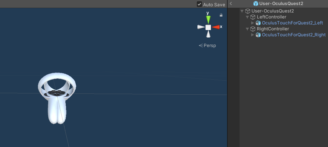
Hierarchy
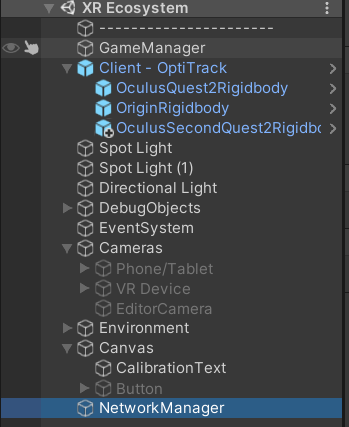
In the following picture we can see the project's hierarchy. There are some important elements that need to be discussed and explained.
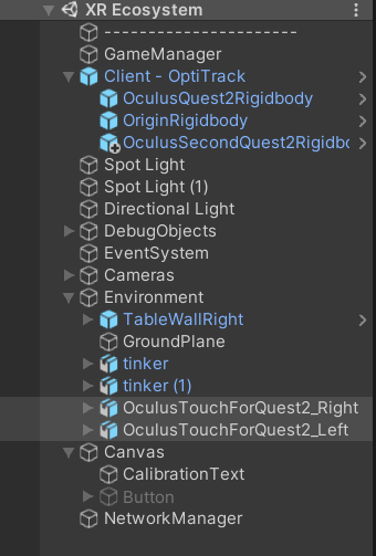
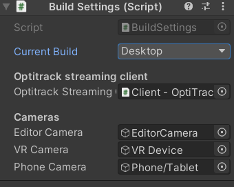
The first thing we are going to look at is the GameManager gameobject. This gameobject contains two scripts: GameManager and BuildSettings. In the first script the basic configuration strings are located that are going to be used in order to store crucial information about the player (regarding how much they changed orientation and position in order to be aligned) also it contains an instance of our player. The BuildSettings script is basically the one that configures where we are building our current scene. The user can choose one of the many devices and automatic configuration would be imported for each device such as what IP should the Optitrack stream data to and what camera to enable (Oculus Quest and desktop have different types of cameras). We also included options for all devices and this should be for later use.
The next gameobject we are to reference is Client-Optitrack. This gameobject hosts as children all the rigidbody that we are defining in Motive. Every new rigidbody that is created should be placed inside it so that it follows the current system architecture. Next on the list but it is not seen in the hierarchy is our player. The player script contains only two properties that are configured through the build settings. The first property is what XR device the player is using and the second one is what is the rigidbody id that is assigned to it. After being defined in the BuildSettings the setup is automatic. The project is built using the S.O.L.I.D principles so that more people will be able to build into it. Last but not least, we see a canvas gameobject with a text in it. This plays a role as a reminder and informs our user of the calibration status. This text has three states. The text is displayed behind our scene so that it would not be so obtrusive to our player. According to the calibration of the user it will inform him/her if he/she has to calibrate his device, save the calibration or everything is ok and it will not display anything.
Setting up the environment
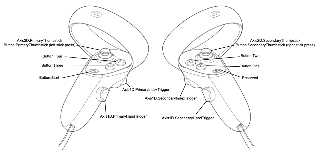
When the player first builds the application for Oculus Quest he/she would start either at the starting position of the Quest or at the position of the Rigidbody marker. This would depend if the marker is detected by the Optitrack when the user starts the application. In our application we are currently using 3 controller buttons: A,B,X (One, Two, Three).
At the first time starting it, a text will appear saying that the user would have to calibrate. The user would then have to place the controllers in the controller holder and then press A. When he/she presses A the virtual controllers would be aligned with the real controllers. Then he/she will have to look if the calibration is ok or he/she will do it again. The next step is to press B in order to save the calibration data. We save the positional and rotational offset of our headset.
We need to save the data in case the headset is not recentered. If we save the data in the current headset position and we don't recenter it, we can reuse it. In case a recenter event is triggered then the user would have to press the X button so that he/she would delete the saved calibration data and then do the same process as described above. After this process then he/she will be able to freely move around the virtual/real environment.
Adding a second Oculus Quest 2
After we managed to get the alignment with the virtual and real world right we needed to see how our scene functions when we added a second Oculus Quest 2.
Photon
In our application we needed a network solution that is specifically built and optimized for Unity. The most famous one is Photon and uses the PUN service for our application. Photon is very easy to use and very effective in simple networking tasks, it cannot be used to deliver vast amounts of data.
When we previously talked about the scene hierarchy we never explained one element. The gameobject called NetworkManager.
This script is basically the handler of all the networking processes. It contains two additional scripts: NetworkManager and NetworkPlayerSpawn. The first script basically connects a player into a room, if there exists one. If there is not a room then the first player would have to create it. Then we also specify our room options such as maximum number of players, determine if the room is open or not and if it is visible to other players. We then override two functions that can help us determine the events of when the user and others join the room.
NetworkPlayerSpawn is the script that determines how the player would appear in the game. When a VR player enters a room then we need to stream the data that the Oculus is giving us about the controllers. We won't stream the data of the headset because we are using the Optitrack to stream its position. We then create a gameobject, which is our player which consists of one parent object and two controllers.
This player holds three scripts, a PhotonView component, which is basically the basic element of a gameobject that needs to be streamed in Photon. It contains a PhotonTransformView component which tells Photon that we are going to synchronize the position and the rotation of our gameobject. Last but not least, it holds the script of OculusNetworkPlayer, where all the synchronization happens. In this script we create an instance of our player both in our game instance and the other instances of the players, then we stream the controller data we are getting from the Oculus Quest. With this procedure all the instances are updated and the other players that join the game are able to see the VR player.
Apart from synchronizing the position of the controllers, which is easy since the data we are using comes from the Oculus Quest we also need to synchronize the calibration data. The difference between these two is that the controller data is continuously streamed and thus we don't need to check anything, on the other hand we need to inform all the other clients that a Quest has been calibrated, so we are using something called PhotonEvent. PhotonEvent is basically what its name implies: it is a network event that triggers when a specific action happens.
Then when the user presses the A button to calibrate him/herself Photon will inform all the clients that this specific action happened and it will update the position of the user in all the instances.
Creating a sample application
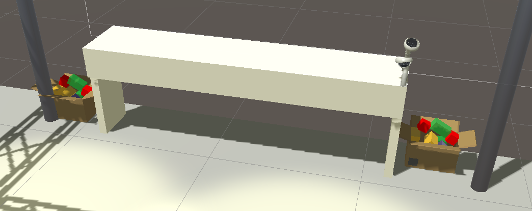
After creating and adding a second Quest we then proceeded to create a sample application in order to test our environment. This application was very simple and was built just to see how co-located VR experiences were. As mentioned previously when a player joins a game he/she must calibrate the headset so that it will be aligned with the environment. After the two players finish the calibration the "Master" client would join. For our application we thought that the "Master" client would be the desktop since it can see both players. When setting the BuildSettings as Desktop the player would have to choose what kind of game the VR environment will include. For this internship we only made one called VR Cleanin.
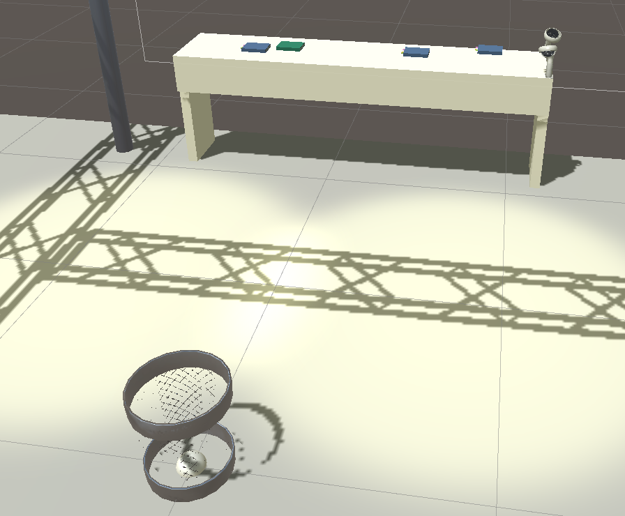
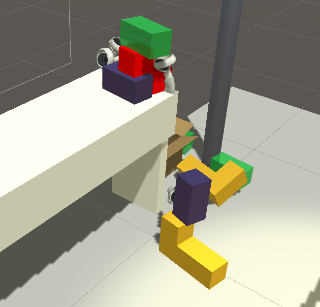
The game is really simple, random objects will appear on the desk (books, stickers etc) and the players would have to take them and place them on a bin that is located in the center of our play area. These objects would appear in random intervals and currently there are no termination conditions, since it was only experimental and only to test the co-located space. In order to test further the functionality of the application I made a second game called Lego. In this game the players would have boxes in the edges of the table where they can grab their lego pieces and start creating things together.
Conclusion & Future Goals
In this internship the goal was to start building an XR space and framework for many devices, although it was not achieved for many devices, we were capable of building an application that consists of two VR devices. This application is built in such a way that is expandable and very easy to use (S.O.L.I.D principles). This expandability also means more games and applications in the same space since creating an application is decoupled from the system�s code. The application was very challenging to build, it required deep knowledge of motion tracking systems and coordinate systems. It was the most arduous task I have faced yet to this day, but it gave me a lot of knowledge for future use. The next goals are of course to implement different kinds of VR devices such as VR devices such as HTC Vive and even AR devices such as a phone or Hololens and to create a robust system for research purposes.