VR Mechanic
Motivation
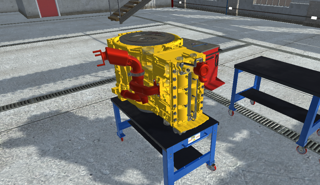
The main idea behind this project is the value that VR applications can offer for training purposes. We imagine that in the future, VR in combination with AR will be used in order to create training scenarios. In our case we only use VR. The training scenario that we want the user to be accustomed to is the assembly and disassembly of an engine. For our example we are using this type of engine that is used mostly on ships.
Implementation
As I said in this scenario we need to train our user into the assembly and the disassembly of the engine. In order to create something like that we use something called a "Snap Zone". This "Snap Zone" functions as an area that indicates where a certain part fit or not. In order to integrate that to our application we used the **VRTK** plugin since it comes with many predefined objects especially concerning VR.

The **VRTK** plugin is one of the most popular plugins for VR since it has many commonly used functionalities. In our project we use for the "Snap Zone" and as well as for the locomotion. In this VR project the locomotion technique that we are using is teleportation. It is easy to integrate, since it is one of the most common in VR. The user is able to teleport using the right analog stick, select where he/she is going to land and according to how much he/she is rotating the stick, it determines how the user looks. The locomotion technique is similar to most techniques used in VR games, in order to avoid motion sickness. In order for our teleportation to be effective, we added certain "targets" at the edges of our table. These targets serve as "cliping points" where the player is able to snap and teleport to.
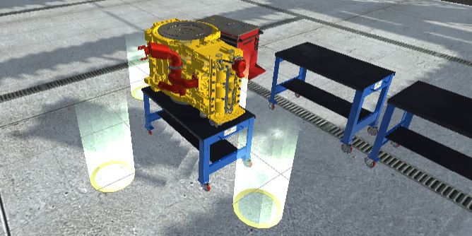
These targets will allow the user to position him/herself in certain parts of the engine in order to be able to assemble and dissasemble it easier. Now we are to start explaining our project. First, we are going to talk about the logic behind our application. We need our application to be as dynamic as possible, meaning that when given a new 3d model of engine dynamic relations between its parts will be created. In order to do that we follow a certain logic. The first thing we do is we specify the properties of our parts. Each part has 4 states, which we call as status:
public enum Status
        {
            Connectable,
            Disconnectable,
            Grabbable,
            Ungrabbable
        }
Each status determine how the user is able to interact with that specific part. For example when the part is Connectable, it means that this part can now connect to another part. Then we need to define which part connects to another part. This is done with an Enumerator we call Type. This enumerator adds a property to our part, that is going to be used by other parts. In each part we utilize a script called EnginePart. This script determines what this part is and as well as creates the relation between this part and other parts.
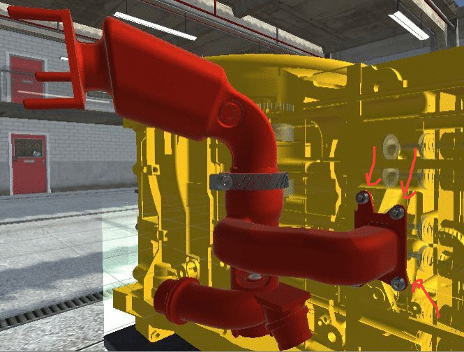
We need to determine all the relations each part has with other objects, because this determines its status. For example let's say we have 4 parts that are connected together, like we see in the picture, the red tube that is located in the side of our engine.
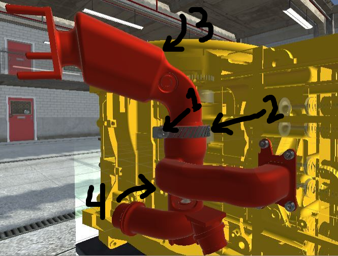
In order to remove the red pipe, we need first to remove the bolt along with the part type that holds the pipe. When the bolt is removed (numbered as 1), we can proceed to remove the part type that holds the pipe (numbered as 2) and following the same procedure, we remove all the parts and release that part from our engine. This is the logic behing the disassembly, pretty easy to follow and it is the first thing I did in that project. I then needed a way to put them back, in case need for an assembly. This is where the "Snap Zone" comes into play. The "Snap Zone" is very valuable to us, since with that we are able to put the part at its starting position. So we store its position at the beggining, in order to know where the part is going to be assembled to. With this information we can start assemblying and disassemblying. At this first video, I created a simple assembly and disassembly procedure.
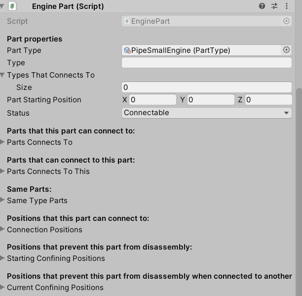
We then move to the next part, creating dynamic relations. As we mentioned earlier the engine part holds all the information we need and now I am going to explain each field. In order to determine the part, we add a scriptable object called "Part type" which basically determines what this part is and with which parts it connects to. Then the "Part Type" automatically fills the fields: Types That Connects to and Type. The next field we are filling is Part Starting Position in order to know where every part is located. The Status field is the only one that is determined while using the application and not on the start of it. We then determine all the other fields, because it will help us check anytime if our part is able to connect or not. If a part is Connectable then the user will be able to grab it and put it into place. We have to note that since some parts can fit into multiple positions. For example a screw, a screw with certain dimensions can fit into many different holes, so some parts do not have a unique position. So we also need to determine all possible positions each part can connect.
After we determine all possible positions, we need to also specify what they are restricting when they are placed in that position and also what they are resctricted by. When we finally we determine that, our relationships are figured out and as result we are able to create them dynamically. All this procedure is done at the beggining of the application and the result can be seen in the next video, where more than 40 engine parts are removed and then added again.